To Download Datasheets Select Below and Click Download
-
Download TDS Datasheet
VT-770 / VT-770(LK) Laminate/Prepreg
UL Approval: E214381 Version: 23/06/2023General Information
- Halogen Free & High Tg (260˚C DMA)
- Low Dk & Very Low Df
- Excellent Thermal Reliability
- High Modulus, Low CTE
- Suitable for CSP, FCP, SiP, AiP, BGA & PGA, etc.
Application
- Handheld Equipment
- High Frequency & High Speed Applications
- Satellite Communications
- Navigation, GPS, LTE
Availability
- Core Thickness: 0.0012” (0.03mm) to 0.031” (0.8mm), available in sheet or panel form
- Copper Foil: 1/7oz (5μm) to 2oz (70μm)
- Prepregs are available in roll or panel form
- Thickness 0.02mm to 0.1mm
Properties Prepreg Laminate Storage Condition Temperature Below 23°C (73°F) Below 5°C (41°F) Room Relative humidity Below 55% RH / / Shelf Life 3 months 6 months 24 months (airproof) The prepreg exceeding shelf life should be retested.
Properties Sheet
Properties Test Method Units Specification VT-770 VT-770(LK) Thermal Properties Tg TMA IPC-TM-650 2.4.24.4 °C 170 minimum 230 230 DMA IPC-TM-650 2.4.24 °C 170 minimum 260 260 Td ASTM D3850 °C 340 minimum 450 450 T260 IPC-TM-650 2.4.24.1 Minute 30 minimum >60 >60 T288 IPC-TM-650 2.4.24.1 Minute 15 minimum >60 >60 Thermal Stress @ 288°C IPC-TM-650 2.4.13.1 Second Pass 10s >600 >600 Z-axis CTE Before Tg IPC-TM-650 2.4.24 ppm/°C 60 maximum 25 22 XY-axis CTE IPC-TM-650 2.4.24.5 ppm/°C - 9~10 9~10 Electrical Properties DK (RC 50%) @ 1GHz IPC-TM-650 2.5.5.9 - - 3.5~3.6 3.4~3.5 @ 10GHz IPC-TM-650 2.5.5.13 - - 3.4~3.5 3.3~3.4 DF (RC 50%) @ 1GHz IPC-TM-650 2.5.5.9 - - 0.0030 0.0020 @ 10GHz IPC-TM-650 2.5.5.13 - - 0.0040 0.0024 Volume Resistivity After Moisture Resistance IPC-TM-650 2.5.17.1 MΩ-cm 1.0E+4 minimum 5.0E+8 5.0E+8 E-24/125 IPC-TM-650 2.5.17.1 MΩ-cm 1.0E+3 minimum 5.0E+6 5.0E+6 Surface Resistivity After Moisture Resistance IPC-TM-650 2.5.17.1 MΩ 1.0E+4 minimum 5.0E+7 5.0E+7 E-24/125 IPC-TM-650 2.5.17.1 MΩ 1.0E+3 minimum 5.0E+6 5.0E+6 Electrical Strength IPC-TM-650 2.5.6.2 Volt/mil (KV/mm) 762 (30) minimum 1400 (55) 1400 (55) Dielectric Breakdown IPC-TM-650 2.5.6 KV 40 minimum 60 60 Comparative Tracking Index (CTI) ASTM D3638 Rating (Volt) - Grade 3 (175~250) Grade 3 (175~250) Arc Resistance ASTM D495 Second 60 minimum 195 195 Mechanical Properties Peel Strength (12μm) As received IPC-TM-650 2.4.8 lb/in (N/mm) - 4.0 (0.7) 4.0 (0.7) After thermal stress IPC-TM-650 2.4.8 lb/in (N/mm) 3.0 (0.52) 4.0 (0.7) 4.0 (0.7) Flexural Modulus Warp/Fill IPC-TM-650 2.4.24.4 GPa - 24~28 24~28 Physical Properties Moisture Absorption IPC-TM-650 2.6.2.1 % 0.80 maximum 0.10 0.10 Flammability UL-94 Rating V-1 minimum V-0 V-0 All test data provided are typical values and not intended to be specification values. Disclaimer: The information and data contained in this technical literature is based on data and knowledge correct at the time of publishing/printing and is believed to be accurate and is offered in good faith for the benefit of the user. The user should make his own tests to verify the suitability of this product for any application before its use. All data are typical values only and subject to change without notice.
Published on: 23/06/2023
-
Download PGL Datasheet
VT-770 / VT-770(LK) Laminate/Prepreg
UL Approval: E214381 Version: 03/02/2025Storage Condition & Shelf Life
Prepreg Laminate Storage Condition Temperature Below 23℃ (73℉) Below 5℃ (41℉) Room Relative Humidity Below 55% / / Shelf Life 3 Months 6 Months 24 Months (airproof) Prepreg exceeding shelf life should be retested.
Precautions in Handling
- The prepreg exceeding shelf time should be retested.
- Take care in handling thin core laminates as they are easily damaged.
- If the prepreg is not consumed within 48hrs after opening the vacuum package, it is recommended that the bags be resealed.
- Material is available in both long and short grain. The grain direction is indicated on the label with an arrow.
Designing and Inner Layer Process
- Please be careful when single ply of 1080, 1086, 1078 or 106 prepreg is designed to the dielectric layer.
- Baking of material is recommended for stabilization of dimension.
- In case of thin copper(ex.3μm) with carrier copper foil, the carrier foil should be removed off before baking.
Baking condition: Temp 200ºC 2 hours;
- Brown Oxide can be used. In the case of using Black Oxide, please check whether peel strength is acceptable for the usage;
- Holding time between brown oxide and press process: best control within 6 hours.
Prepreg Availability
E-Glass styles: 2116, 3313, 1078, 1067,1037,1035, etc. Dk values are for impedance designVT-770
Delivered Thickness (mm) Glass Style Resin Content Dk Df @ 1GHz @ 2GHz @ 5GHz @ 10GHz @ 20GHz @ 1GHz @ 2GHz @ 5GHz @ 10GHz @ 20GHz 2.0 1037 74% 3.27 3.27 3.23 3.19 3.16 0.003 0.0034 0.0037 0.0039 0.0041 2.4 1067 71% 3.33 3.33 3.27 3.23 3.19 0.003 0.0035 0.0038 0.004 0.0042 2.6 1067 73% 3.28 3.28 3.22 3.18 3.15 0.003 0.0034 0.0037 0.0039 0.0041 2.9 1067 75% 3.25 3.24 3.20 3.16 3.13 0.003 0.0034 0.0037 0.0039 0.0041 3.3 1078 66% 3.40 3.40 3.35 3.31 3.27 0.0031 0.0036 0.0039 0.0041 0.0043 3.5 1078 68% 3.33 3.32 3.26 3.22 3.19 0.003 0.0035 0.0038 0.004 0.0042 4.0 3313 56% 3.48 3.48 3.43 3.39 3.34 0.0033 0.0038 0.0041 0.0043 0.0045 5.0 2116 54% 3.50 3.49 3.45 3.41 3.38 0.0033 0.0038 0.0041 0.0043 0.0045 VT-770(LK)
Delivered Thickness (mm) Glass Style Resin Content DK DF @ 1GHz @ 2GHz @ 5GHz @ 10GHz @ 20GHz @ 1GHz @ 2GHz @ 5GHz @ 10GHz @ 20GHz 2.1 1035 67% 3.00 2.98 2.95 2.91 2.88 0.0018 0.0020 0.0022 0.0024 0.0026 2.3 1035 71% 2.92 2.90 2.88 2.83 2.80 0.0018 0.0020 0.0022 0.0024 0.0026 2.7 1035 75% 2.85 2.83 2.80 2.75 2.72 0.0017 0.0019 0.0021 0.0023 0.0025 3.0 1078 67% 3.00 2.98 2.95 2.91 2.88 0.0018 0.0020 0.0022 0.0024 0.0026 3.5 1078 71% 2.92 2.90 2.88 2.83 2.80 0.0018 0.0020 0.0022 0.0024 0.0026 3.9 1078 74% 2.87 2.85 2.83 2.78 2.75 0.0017 0.0019 0.0021 0.0023 0.0025 4.2 3313 63% 3.05 3.03 3.00 2.96 2.93 0.0020 0.0022 0.0024 0.0026 0.0028 5.0 2116 59% 3.12 3.10 3.07 3.03 3.00 0.0020 0.0022 0.0024 0.0026 0.0028 Remark: ① Press thickness test condition---Prepreg lamination size 18”*24”, Copper Foil---1oz/1oz, Flow---about 5%; ② Make laminated prepreg to micro-section and measure the thickness with microscope; this thickness is used for resistance design calculation. ③ The thickness measured with micrometer is 0.2~0.4 mil larger than that measured with micro-section; and mainly used for total thickness design calculation.
Laminate Availablity
Dk values are for impedance designVT-770
Laminate Thickness (mm) Glass Style Piles Resin Content Dk Df @ 1GHz @ 2GHz @ 5GHz @ 10GHz @ 20GHz @ 1GHz @ 2GHz @ 5GHz @ 10GHz @ 20GHz 1.7 1027 1ply 73% 3.28 3.28 3.22 3.18 3.15 0.003 0.0034 0.0037 0.0039 0.0041 2.0 1067 1ply 65% 3.40 3.40 3.35 3.31 3.27 0.0031 0.0036 0.0039 0.0041 0.0043 2.4 1067 1ply 69% 3.33 3.32 3.26 3.22 3.19 0.0030 0.0035 0.0038 0.0040 0.0042 3.0 1078 1ply 64% 3.42 3.41 3.36 3.33 3.29 0.0031 0.0036 0.0039 0.0041 0.0043 3.5 1078 1ply 68% 3.35 3.35 3.29 3.25 3.21 0.0030 0.0035 0.0038 0.0040 0.0042 4.0 3313 1ply 56% 3.48 3.48 3.43 3.39 3.34 0.0033 0.0038 0.0041 0.0043 0.0045 4.0 1067 2ply 65% 3.40 3.40 3.35 3.31 3.27 0.0031 0.0036 0.0039 0.0041 0.0043 5.0 2116 1ply 54% 3.50 3.49 3.45 3.43 3.38 0.0033 0.0038 0.0041 0.0043 0.0045 5.0 1078 2ply 58% 3.47 3.47 3.42 3.38 3.34 0.0033 0.0037 0.0041 0.0043 0.0045 6.0 1078 2ply 63% 3.44 3.44 3.39 3.35 3.31 0.0031 0.0036 0.0039 0.0041 0.0043 8.0 3313 2ply 56% 3.48 3.48 3.43 3.39 3.34 0.0033 0.0038 0.0041 0.0043 0.0045 12.0 3313 3ply 56% 3.48 3.48 3.43 3.39 3.34 0.0033 0.0038 0.0041 0.0043 0.0045 More types could be available upon request.
VT-770(LK)
Laminate Thickness (mm) Glass Type Piles Resin Content Dk Df @ 1GHz @ 2GHz @ 5GHz @ 10GHz @ 20GHz @ 1GHz @ 2GHz @ 5GHz @ 10GHz @ 20GHz 2.0 1067 1ply 69% 2.95 2.93 2.90 2.85 2.82 0.0018 0.0020 0.0022 0.0024 0.0026 2.6 1078 1ply 65% 3.05 3.03 3.00 2.96 2.93 0.0019 0.0021 0.0023 0.0025 0.0027 2.6 1037 2ply 65% 3.05 3.03 3.00 2.96 2.93 0.0019 0.0021 0.0023 0.0025 0.0027 3.0 1078 1ply 67% 3.00 2.98 2.95 2.91 2.88 0.0018 0.0020 0.0022 0.0024 0.0026 4.0 3313 1ply 60% 3.10 3.08 3.05 3.01 2.98 0.0020 0.0022 0.0024 0.0026 0.0028 4.0 1067 2ply 69% 2.95 2.93 2.90 2.85 2.82 0.0018 0.0020 0.0022 0.0024 0.0026 4.5 3313 1ply 63% 3.05 3.03 3.00 2.96 2.93 0.0020 0.0022 0.0024 0.0026 0.0028 4.5 1067 2ply 72% 2.92 2.90 2.88 2.83 2.80 0.0018 0.0020 0.0022 0.0024 0.0026 5.0 2116 1ply 58% 3.12 3.10 3.07 3.03 3.00 0.0020 0.0022 0.0024 0.0026 0.0028 5.0 1067 2ply 75% 2.85 2.83 2.80 2.75 2.72 0.0017 0.0019 0.0021 0.0023 0.0025 6.0 1078 2ply 67% 3.00 2.98 2.95 2.91 2.88 0.0018 0.0020 0.0022 0.0024 0.0026 8.0 3313 2ply 60% 3.10 3.08 3.05 3.01 2.98 0.0020 0.0022 0.0024 0.0026 0.0028 10.0 2116 2ply 58% 3.12 3.10 3.07 3.03 3.00 0.0020 0.0022 0.0024 0.0026 0.0028 More types could be available upon request.
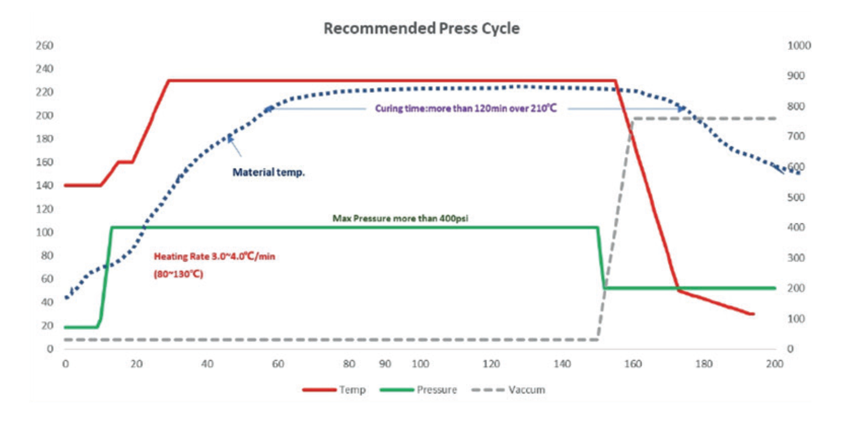
Press Condition
1. Heating rate (Rate of Rise) of material [Material Temperature]: Programmable Press: ≥3ºC/min
2. Curing Temperature & Time: >120min at more than 210ºC and peak temperature>215 ºC
3. Full Pressure: ≥400psi (28Kg/cm2) should be applied full pressure before 100 ºC
4. Vacuuming should be continued until over 140ºC [Material Temperature]
5. Cushion for pressure evenness is needed
Typical Drilling Parameters
- Drilling parameters should be adjusted depending on hole size, layer count, panel thickness, stack count and stack height etc.
- Please adjust drilling parameters after checking qualities of through holes.
- Suggest Drilling parameter as below:
Diameter (mm) Spindle Speed (krpm) Feed Rate (IPM) Chip Load (IPM) Hit Counts 0.10 200~300 25~38 800 1000 0.20 150~200 38~50 800 1000 0.30 100~150 38~60 800 1000 0.40 80~100 40~50 800 1000 Smear, resin cracking or nail heading may occur if drilling condition doesn’t match material.
Desmearing Process
- The weight loss of VT-770 &VT-770(LK) is less than as our conventional FR-4 material.
- We recommend a plasma cycle and a vertical permanganate cycle together to adequately prepare the hole walls for plating
(If used by horizontal desmear, it should be need twice cycles).
- Plasma Desmear Parameter
One time of FR-4 conditions is recommendable.
- Permanganate Desmear Parameter
Twice of FR-4 horizontal desmear condition is recommendable, or one time of FR-4 vertical desmear condition is recommendable.
- Typical Permanganate Desmear parameter by Atotech chemical as below:
Process Reagent Type Temperature ℃ Duration (min) Sewll Alkaline 60-70 5-10 Etching Permanganate 70-80 10-15 Please consult the chemical supplier for suggested conditions.
Packaging and Baking Recommendation
- It is recommended to bake the board before packaging at 125ºC/4~8h to avoid moisture causing a decrease in heat resistance.
- If the PCBs needs to be stored for a long time before use, it is recommended to use aluminum foil vacuum packaging.
- If exceed 3 months after packaging , It is best to bake the PCBs at 125ºC/4~6h before assembly before use.