To Download Datasheets Select Below and Click Download
-
Download TDS Datasheet
Thermal-bond 7.0F VT-4BC RCF Thermally Conductive Resin Coated Film Bondply
UL Approval: E214381 Version: 13/01/2025 Resin Coated Film (RCF) Thermal bond is an unreinforced adhesive system coated onto PET/PI film for use in high performance and high reliability multilayer PCB stack-ups. VT-4BC RCF is a high Tg, ceramic-filled, thermally conductive (9.0 W/mK), halogen-free thermoset resin system, specifically designed for use in multilayer PCBs requiring enhanced levels of heat management and thermal conductivity. Thermal bond RCF can be combined with other Ventec laminate & prepreg systems including tec-thermal IMS, VT-5A2 and VT-4A2H thermally conductive laminates & prepregs in hybrid stack-ups.General Information
- Thermal conductivity -- 9 W/mK
- Tg 210˚C
- Ceramic Filled
- Halogen Free
- Flammability (UL94 V-0)
- UL MOT 155˚C
- Easy handling (like rubber)
Application
- Good Adhesion
- High Working Voltage [≥500Volts]
- Heavy Copper Filled
- Power Conversion
- Monitor Drives
- Rectifiers, Power Supply
- Metal in Board (MiB) applications including Coins and Inserts, Pedestal, etc
Availability
Press Ply Thickness 120µ/150µ (0.005”/0.006”) Description Part Number PPT (µm) Flow Range Panel Size 460*610mm, 510*610mm, 533*610mm, 18.11*24.02”, 20.08*24.02”, 20.98*24.02”. or as required thermal-bond 7.0F RCF Regular Flow PPT 120µm 4BC-FT R-120 120 40~80 thermal-bond 7.0F RCF Regular Flow PPT 150µm 4BC-FT R-150 150 60~100 Carrier Film Type PET (Standard) T PI (as required) I Properties
Properties Sheet
Properties Test Method Units 120um 150um Thermal Conductivity ISO 22007-2 W/m*K 9.0 Thermal Impedance ISO 22007-2 ˚C *in2/W 0.021 0.026 Tg DMA IPC-TM-650 2.4.24.4 °C 210 Td TGA ASTM D3850 °C 400 Thermal Stress @ 288˚C solder dip IPC-TM-650 2.4.13.1 Minute ≥5 Hi-Pot Withstand DC IPC-TM-650 2.5.7 Volt >600 Breakdown Voltage AC IPC-TM-650 2.5.6.3 Volt 8000 10000 Electrical Properties Dk @ 1MHz C-24 / 23 / 50 IPC-TM-650 2.5.5.3 - 4.25 Df @ 10GHz 4.57 Dk @ 1MHz C-24 / 23 / 50 IPC-TM-650 2.5.5.3 - 0.0015 Df @ 10GHz 0.0017 Volume Resistivity After Moisture Resistence IPC-TM-650 2.5.17.1 MΩ-cm 5.0E+8 E-24/125 3.0E+7 Surface Resistance After Moisture Resistence IPC-TM-650 2.5.17.1 MΩ 2.0E+7 E-24/125 5.0E+6 Mechanical Properties Peel Strength (1oz) As received IPC-TM-650 2.4.8 lb/in 4.3 CTI As received ASTM D3638 Volt 600 Physical Properties Flammability As received UL-94 Rating V-0 Note: All test data provided are typical values and are not intended to be specification value.
Storage Condition
RCF Storage Condition Temperature < 23˚C (73˚F) < 5˚C (41˚F) Relative Humidity < 55% / Disclaimer: The information and data contained in this technical literature is based on data and knowledge correct at the time of publishing/printing and is believed to be accurate and is offered in good faith for the benefit of the user. The user should make his own tests to verify the suitability of this product for any application before its use. All data are typical values only and subject to change without notice.
-
Download PGL Datasheet
Thermal-bond 7.0F VT-4BC RCF Bondply
UL Approval: E214381 Version: 26/06/2025RCF Storage Condition Temperature Below 23℃ (73℉) Below 5℃ (41℉) Relative Humidity Below 55% / Shelf Life / 2 Months Prepreg exceeding shelf life should be retested.
Precautions in Handling
- The thermal management prepreg should be taken care of when handling and wearing rubber gloves to prevent contamination is strongly recommended during processing.
- It is strongly recommended that the remaining loose packages be sealed as soon as possible and stored in a cold storage.
Product Handling & Press Process Flow
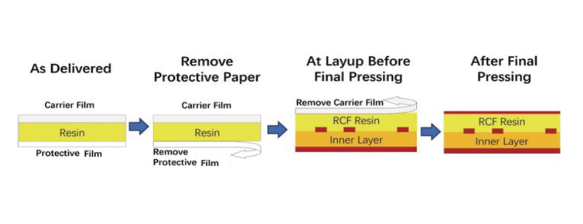
1. Please put RCF on a clean and flat surface with the PET film side up in cleanroom.
2. Please pay more attention to the alignment of RCF colloid edge with the substrate or metal plate.
3. When tearing off the PET film from the resin, perform the action gently starting from one corner.
4. Then put copper foil or another piece of RCF on the surface.
5. It is recommended to be careful when handling.Disclaimer: The information and data contained in this technical literature is based on data and knowledge correct at the time of publishing/printing and is believed to be accurate and is offered in good faith for the benefit of the user. The user should make his own tests to verify the suitability of this product for any application before its use. All data are typical values only and subject to change without notice.
Press Parameters
1. Heating rate (Rate of Rise) of material (60~110ºC) [Material Temperature]: 2.5~4.0ºC/min
2. Curing Temperature & Time: >80min at more than 180ºC [Material Temperature]
3. Full Pressure: ≥ 420psi, It’s should be started before 70ºC of material temperature
4. Vacuuming should be continued until over 180ºC [Material Temperature]
5. Cold Press condition: Keep Plate @ Room Temperature by water; Pressure: 100psi; Keep Time: 60minutes
6. Also it is recommended to add a three-in-one cushion film between the copper foil and the steel plate on the RCF side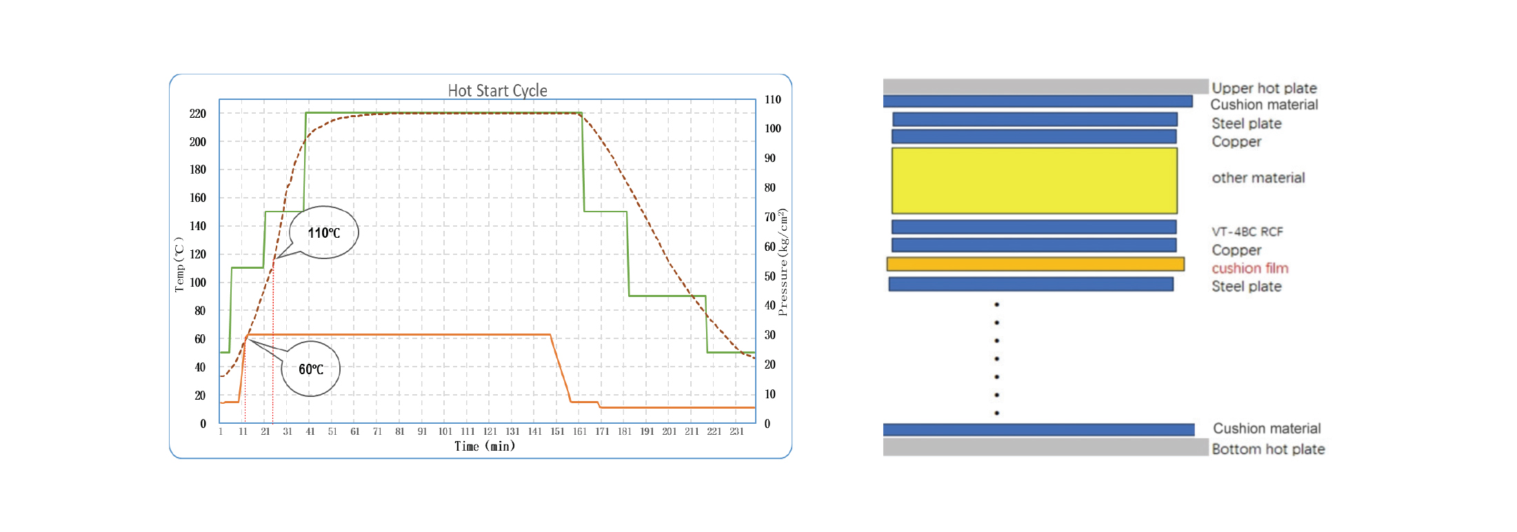 a) Please put RCF on a clean and flat surface with the PET film side up in cleanroom.
b) Please pay more attention to the alignment of RCF edge with the substrate or metal plate.
c) Start from one corner when peeling off the PET film from resin.
a) Please put RCF on a clean and flat surface with the PET film side up in cleanroom.
b) Please pay more attention to the alignment of RCF edge with the substrate or metal plate.
c) Start from one corner when peeling off the PET film from resin. Baking Recommendation During PCB Process
Process Purpose Cycle Potential risk without bake Before HASL, PCB should be separate (not stacked) and supported in a rack for this process. HASL process should be finished within 24 hours after baking finishing To eliminate moisture 2 hours @ 125°C Potential for measling, blister and de-lamination Before shipment, if PCB stored for > 1 month, purpose to eliminate moisture cycle potential risk 2 hours @ 125ºC PCB should be baked before packaging To eliminate moisture 2~4 hours @ 125°C Potential for measling, blister and de-lamination Prepreg exceeding shelf life should be retested.
Typical Drilling Conditions
Without Metal Base (only for reference)With Metal Base (only for reference)Diameter (mm) Stack Height Spindle Speed (KRPM) Feed Rate (mm/s) Retract Rate (mm/s) Hit Count 0.15 1 PNL/stack 155 17 200 800 0.20 1 PNL/stack 145 20 200 800 0.25 1 PNL/stack 130 27 200 800 0.30 1 PNL/stack 125 33 250 800 0.35~0.40 1 PNL/stack 110 40 250 800 0.45 1 PNL/stack 100 47 250 800 0.50 1 PNL/stack 95 47 250 800 0.55 1 PNL/stack 88 47 330 800 0.60 1 PNL/stack 80 47 330 800 0.65 1 PNL/stack 74 47 330 800 a) Carbide drill bit is prone to excessive wear, preferably Jinzhou SHD/MDC series drill bit. b) Aluminum and Phenolic Board Covers are recommended.
Diameter (mm) Stack Height Spindle Speed (KRPM) Feed Rate (mm/s) Retract Rate (mm/s) Hit Count 0.25 1 PNL/stack 80 20~25 100~200 600 0.30 1 PNL/stack 40 20~25 100~200 500 0.60 1 PNL/stack 40 20~30 100~200 500 0.7~0.9 1 PNL/stack 40 30~40 300~400 400 1.0~1.5 1 PNL/stack 39 40~50 350~450 300 2.0~2.5 1 PNL/stack 38 35~45 250~350 200 a) Carbide drill bit is prone to excessive wear, preferably Jinzhou SHD/MDC series drill bit b) Recommend Aluminum and Phenolic Board Covers
Image Transfer
Process Recommendation Dry Film The lamination speed maybe needs slower than standard FR4 to have metal substrate approach proper lamination temperature Wet Film Both aluminum and copper could be coated to protect aluminum during etching process. Follow instruction details of manufacturers Developing Masking or film protection on aluminum is better during developing. Follow chemical manufacturer’s recommendation • Dry filming and wet filming are both applicable process on aluminum base laminate • Before filming, cleaning of panel surface is necessary • Wet film process options: - Curtain - Screen
Etching Stripping
Process Recommendation Etching Alkaline or acid solution (cupric chloride, ferric chloride) are both applicable. Alkaline etching is faster than acid etching and is fit for below 3oz copper. The acid etching performs well on preventing of undercut and over etch Stripping Apply sodium hydroxide solution to remove etch resist and conveying process is preferred Solder Masking
Process Recommendation Solder Masking Control the thickness between 1~2mil or depends on boards design Pre-heating Follow manufacturer’s recommendation on the setting of temperature and time. Having a filter system in oven is preferred Developing Solution concentration, temperature and spray pressure need to be controlled Curing Follow the details of temperature and time of manufacturer. • Roughness of board surface is necessary to get better adhesion between boards and solder mask • Before filming, cleaning of panel surface is necessary • Both thermal cured and UV cured solder mask are applicable • Masking options: - Screen Printing - Curtain Coating - Spray Coating - Roller Coating
Surface Finishing Options
Process Recommendation HASL The most popular surface treatment method. Peel off the protective film from aluminum before HASL OSP Follow details of manufacturer’s recommendation ENIG Popular in wire bonding application. Follow chemistry recommendation to avoid defects of black pad and brickle gold Silver Immersion Silver immersion has a better soldering ability but has disadvantage of silver migration Routing
Diameter (mm) Spindle Speed (KRPM) Feed Rate (mm/s) Retract Rate (mm/s) Hit Count 0.8 37 10~15 30 12~15 1.0 37 10~15 30 10~12 1.2 37 12~18 30 8~10 1.5 36 15~20 30 5~8 2.0 34 15~20 30 3~5 • Backup board – Phenolic is preferred • Tools material – Tungsten or Diamond carbite with 2 flutes is preferred • Stack height – 1 panel / stack • Consult your tool supplier for more advice
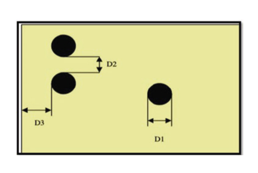
Punching
• Alloy side is upwards when punching • Tonnage – 120T and above is preferred • “D1&D2” should be greater than board thickness • “D3” should be greater than board thickness + 0.5mm • Consult your tool supplier for more advice